The Complete Guide to Hydraulics Systems
From the elevator you take at work to the dump truck you see rolling by on the street, hydraulics are everywhere. You may be wondering what hydraulics are. This powerful system drives some of the heaviest pieces of machinery out there. Hydraulics can lift immense loads and operate at high speeds. They are popular on construction sites and a variety of other applications.
There are many types of hydraulic systems with various components, all of which operate under the same principles of energy. Hydraulic pumps pressurize a liquid, and its movement is used to power everything from cranes to cars. In this article, we’re going to tell you everything you need to know about hydraulic systems.
Explore the Rest of Our Hydraulic Systems Guide:
How Does a Hydraulic System Work?
You’re probably already familiar with some of the basic ways a hydraulic system works and its components. From your experience, you probably know that solids are typically impossible to squish. If you pick up a solid object like a pen or piece of wood and try to squeeze it, nothing’s going to happen to the materials. They won’t compress or squish. Liquid works in the same way. It is incompressible, meaning it won’t squeeze when you apply pressure to it. It takes up the same amount of space as it did when pressure wasn’t applied to it. Picture water in a syringe. If you cap the end of it with your finger and try to press down, neither the water nor the plunger will go anywhere.
Where hydraulic systems are concerned, that incompressibility is a major player in making them work. In that same syringe, if you press down on the plunger normally, you’ll release the water at high speed through the narrow end, even if you didn’t apply that much pressure. When you push down the plunger, you apply pressure to the water, which will try to escape however it can — in this case, at high pressure through a very narrow exit. This application shows us that we can multiply force, which we can then use to power more complex devices.
In a very simplified system, a hydraulic system is made with piping that has a weight or piston on one end to compress the liquid. As this weight depresses onto the liquid, it forces it out of a much narrower pipe at the other end. The water doesn’t squish down and instead pushes itself through the pipe and out the narrow end at high speed. This system works in reverse as well. If we apply a force to the narrow end for a longer distance, it will generate a force capable of moving something much heavier on the other end.
Blaise Pascal, a French mathematician, physicist and inventor, standardized these properties in the mid-1600s. Pascal’s Principle states that, in a confined space, any change in pressure applied to a fluid transmits through the fluid in every direction. In other words, if you apply pressure to one end of a container of water, the same pressure will be applied to the other side. This principle is what allows the force to be multiplied and affect a larger, heavier object.
There is a little bit of a trade-off with this system. You can typically apply more force or more speed to one end to see the opposite result on the other. For example, if you press down on the narrow end with high speed and low force, you’ll apply high force but low speed to the wide end. The distance your narrow end can travel would also influence how far the wide one will move. Trading distance and force is typical in many systems, and hydraulics are no exception.
The multiplication of force is an influential factor in lifting heavy objects. If the piston in the broader side is six times the size of the smaller one, then the force applied to the fluid from the larger piston will be six times as powerful on the smaller end. For example, a 100-pound force down at the wider end creates a 600-pound force up at the narrow end. This force multiplication is what allows hydraulic systems to be relatively small. They are great for powering huge machines without taking up too much space.
Hydraulics can also be very flexible, and there are many different types of hydraulic systems. You can move the fluids through very narrow pipes and snake them around other equipment. They have a variety of sizes and shapes and can even branch off into multiple paths, allowing one piston to power several others. Car brakes are usually an example of this. The brake pedal activates two master cylinders, each of which reaches two brake pads, one for all wheels. You can find hydraulics powering a variety of components through cylinders, pumps, presses, lifts and motors.
Hydraulic systems have a few essential components to control how they work:
- Reservoir: Hydraulic systems usually use a reservoir to hold excess fluid and power the mechanism. It is important to cool the fluid, using metal walls to release the heat generated from all the friction it encounters. An unpressurized reservoir can also allow trapped air to leave the liquid, which helps efficiency. Since air compresses, it can divert the movement from the pistons and make the system work less efficiently.
- Fluid: Hydraulic fluids can vary, but they are typically petroleum, mineral- or vegetable-based oils. The fluids can have different properties based on their application. Brake fluid, for example, needs to have a high boiling point due to the high-heat mechanism it goes through. Other features include lubrication, radiation resistance and viscosity.
Let’s take a look at how hydraulics typically work in heavy equipment:
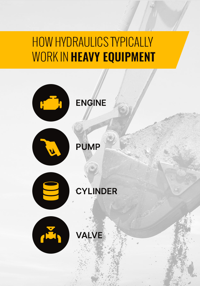
- Engine: This is usually gasoline-powered and allows the hydraulic system to work. In big machines, this needs to be capable of generating a lot of power.
- Pump: The hydraulic oil pump sends a flow of oil through the valve and to the hydraulic cylinder. Pump efficiency is often measured in gallons per minute and pounds per square inch (psi).
- Cylinder: The cylinder receives the high-pressure fluid from the valves and actuates the movement.
- Valve: Valves help to transport the fluid around the system by controlling things like pressure, direction and flow.
Other machines that make use of hydraulics include vehicles on construction sites. Diggers, cranes, bulldozers and excavators can all be run by robust hydraulic systems. A digger, for example, powers its massive arm with hydraulic-powered rams. The fluid is pumped into the thin pipes, lengthening the rams and, by extension, the arm. The hydraulic power behind this can be used to lift enormous loads. Aside from construction machines, hydraulics are used for everything from elevators to motors, even in airplane controls.
What is the Difference Between Open vs. Closed Hydraulic Systems?
Open and closed systems of hydraulics refer to different ways of reducing pressure to the pump. Doing this can help reduce any wear and tear.
In an open system, the pump is always working, moving oil through the pipes without building up pressure. Both the inlet to the pump and the return valve are hooked up to a hydraulic reservoir. These are also called “open center” systems, because of the open central path of the control valve when it is neutral. In this case, hydraulic fluid returns to the reservoir. The fluid coming from the pump goes to the device and then returns to the reservoir. There may also be a relief valve in the circuit to route any excess fluid to the reservoir. Filters are usually in place to keep the fluid clean.
Open systems tend to be better for low-pressure applications. They also tend to be cheaper and easier to maintain. One caution is that they can create excess heat in the system if the pressure exceeds valve settings. Another location for added heat is in the reservoir, which needs to be big enough to cool the fluid running through it. Open systems can also use multiple pumps to supply power to different systems, such as steering or control.
A closed system connects the return valve directly to the hydraulic pump inlet. It uses a single central pump to move the fluid in a continuous loop. A valve also blocks oil from the pump, instead sending it to an accumulator where it stays pressurized. Oil remains under pressure but doesn’t move unless it is activated. A charge pump supplies cool, filtered oil to the low-pressure side. This step maintains pressure within the loop. A closed system is often used in mobile applications with hydrostatic transmissions and uses one pump to power multiple systems.
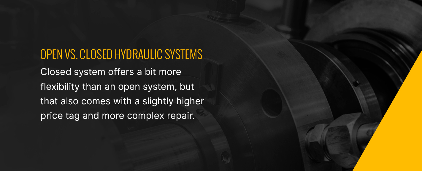
These can have smaller reservoirs because they just need to have enough fluid for the charge pump, which is relatively small. An open system can handle more high-pressure applications. The closed system offers a bit more flexibility than an open system, but that also comes with a slightly higher price tag and more complex repair. Closed systems can work with less fluid in smaller hydraulic lines, and the valves can be used to reverse the direction of the flow.
You can even convert an open system into a closed system by replacing some of the components and adding space for the oil to go after the return trip.
Types of Hydraulic Pumps
There are several different types of hydraulic pumps. These can vary significantly in the ways that they move fluid and how much they displace.
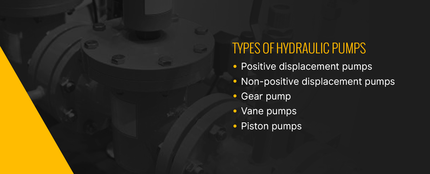
Almost all hydraulic pumps are positive displacement pumps, meaning they deliver a precise amount of fluid. They can be used in high-power applications of over 10,000 psi. Non-positive displacement pumps depend on pressure for the amount of fluid they move, while positive displacement pumps do not. Non-positive pumps are more common in pneumatics and low-pressure applications. They include centrifugal and axial pumps.
Positive displacement pumps can have either fixed or variable displacement. Most pumps fall under fixed displacement.
- In fixed displacement, the pump provides the same amount of fluid in each pump cycle.
- In variable displacement, the pump can provide different amounts of fluid based on the speed it is run at or the physical properties of the pump.
A gear pump is inexpensive and more tolerant of fluid contamination, making them suitable for rough environments. They may be less efficient, however, and wear more quickly.
- External gear pumps: These make use of two tight-meshed gears within a housing. One is the driving, or powered, gear, while the other is driven, or free-flowing. The fluid is trapped in the space in between the gears and rotated through the housing. Since it cannot move backward, it is forced through the outlet pump.
- Internal gear pump: The internal gear design places an inner gear, possibly with a crescent-shaped spacer, inside of an outer rotor gear. The fluid is moved via eccentricity — the deviation of the gear from circularity — between the gears. The inner gear, with fewer teeth, turns the outer gear, and the spacer goes in between them to create a seal. The fluid is drawn in, moved through the gears, sealed up and discharged.
Next up is vane pumps. These can be unbalanced or balanced and fixed or variable-displacement. They are quiet and work in pressures under 4,000 psi.
- Unbalanced vane pump: This fixed displacement pump has a driven rotor and vanes that slide out in radial slots. The rotor’s level of eccentricity determines the level of displacement. As it rotates, the space between the vanes increases, creating a vacuum to draw fluid in. The trapped fluid moves around the system via the rotating vanes and is pushed out as the space between them decreases.
- Balanced vane pump: The balanced vane pump, also fixed displacement, moves the rotor through an elliptical cam ring. It uses two inlets and outlets on each revolution.
- Variable-displacement vane pump: The displacement in this type of pump can change via the eccentricity between the rotor and casing. The outer casing ring is moveable.
Our last category of pumps is piston pumps, which are great for high-powered applications.
- In-line axial piston pumps: In-line pumps align the center of the cylinder block with the center of the driveshaft. The angle of the swash/cam plate helps to determine the amount of displacement. The inlet and outlet are located in the valve plate, which connects to each cylinder alternately. As the piston moves up past the inlet port, it pulls in fluid from the reservoir. Similarly, it will push the liquid out of the outlet port as it passes it.
- Bent-axis axial piston pumps: The bent-axis pumps line the center of the cylinder block at an angle with the center of the drive shaft. This design works similarly to the in-line axial pump.
- Radial piston pumps: A radial piston pump uses seven or nine radial barrels, along with a reaction ring, pintle and driveshaft. The pistons are set radially around the drive shaft, and inlet and outlet ports are in the pintle, a type of hinge.
Learn More About Hydraulics
Now that you know what hydraulics are, you can see that hydraulics have vast applications and can be used in all sorts of different components of the machinery that runs construction, transportation and more. You may even be able to think of some hydraulic system examples of your own now. The power of water has been used for centuries, and now, with the help of valves, pistons and cylinders, hydraulics can run in a variety of different formats. Open and closed, fixed or variable, positive and non-positive — all of these can move massive weights and take advantage of modern engineering. If you run any sort of business, you may be able to put hydraulics to work for you.
At Hard Chrome Specialists, we offer repair services on all types of hydraulic systems as well as plating, electropolishing and custom fabrication. We hope you’ve learned something new today about how hydraulics work and understand a little more about this incredibly powerful system. If you want to learn more about hydraulics, contact us today!